VORTEX LIMITER
CHARACTERISTICS
The VORTEX EFFECT FLOW LIMITER or VORTEX LIMITER is positioned at the outlet of the control structure, on the retention side. It limits the outflow according to the maximum head of water upstream.
Its passage section is at least three times larger than a nozzle hole. The VORTEX EFFECT LIMITER therefore reduces the risk of clogging at the tank outlet. As the flow limiter has no moving mechanism, maintenance is minimal.
The VORTEX LIMITER is available in two configurations:
- A fixed version, installed directly on the concrete wall;
- A removable version, mounted on slides, which can be removed from the surface using a sling.
MATERIAL AND OPTION
- Body: AISI 304 stainless steel;
- Fasteners: AISI 304 stainless steel;
- Foam joint: EPDM.
- Support(1) : HDPE;
(1) For removable limiter
Option :
- Adaptor flange for circular manhole. Consult us.
INSTALLATION / APPLICATION
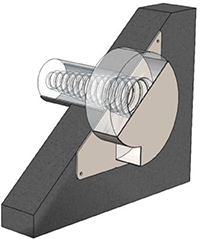
The VORTEX LIMITER requires an increase in an upstream load to operate. The formation of the vortex, that is to say the whirlpool, occurs when the limiter is fully submerged.
Due to hydrostatic pressure, the water begins to swirl in the limiter chamber. The speed of the water, combined with the volute shape of the limiter, causes the effluent to flow around the periphery of the outlet tube. An air cone forms at the centre of the limiter.
It is this air cone that enables the flow limitation while maintaining a large passage section: more than three times larger than a nozzle.
PRODUCT CHOICE
↵
| PRODUCT | 0,5m H.WATER | 1m H.WATER | 1,5m H.WATER | 2m H.WATER | 2,5m H.WATER | 3m H.WATER | Ø MAX(1) |
|---|---|---|---|---|---|---|---|
| LMVORTEX220 | 0,5 à 1,0 l/s | 0,8 à 1,2 l/s | 1,0 à 1,4 l/s | 1,2 à 1,6 l/s | 1,3 à 1,8 l/s | 1,4 à 2,0 l/s | 130 |
| LMVORTEX244 | 1,0 à 1,3 l/s | 1,2 à 1,7 l/s | 1,4 à 2,0 l/s | 1,6 à 2,3 l/s | 1,8 à 2,6 l/s | 2,0 à 2,9 l/s | 150 |
| LMVORTEX258 | 1,3 à 1,7 l/s | 1,7 à 2,2 l/s | 2,0 à 2,7 l/s | 2,3 à 3,1 l/s | 2,6 à 3,5 l/s | 2,9 à 3,7 l/s | 160 |
| LMVORTEX276 | 1,7 à 2,1 l/s | 2,2 à 2,9 l/s | 2,7 à 3,5 l/s | 3,1 à 4,1 l/s | 3,5 à 4,6 l/s | 3,7 à 4,9 l/s | 170 |
| LMVORTEX294 | 2,1 à 2,8 l/s | 2,9 à 3,6 l/s | 3,5 à 4,5 l/s | 4,1 à 5,2 l/s | 4,6 à 5,7 l/s | 4,9 à 6,2 l/s | 185 |
| LMVORTEX334 | 2,8 à 3,6 l/s | 3,6 à 4,7 l/s | 4,5 à 5,7 l/s | 5,2 à 6,5 l/s | 5,7 à 7,2 l/s | 6,2 à 7,8 l/s | 215 |
| LMVORTEX364 | 3,6 à 4,2 l/s | 4,7 à 5,6 l/s | 5,7 à 6,7 l/s | 6,5 à 7,6 l/s | 7,2 à 8,4 l/s | 7,8 à 8,9 l/s | 240 |
| LMVORTEX394 | 4,2 à 5,0 l/s | 5,6 à 6,7 l/s | 6,7 à 8,0 l/s | 7,6 à 9,0 l/s | 8,4 à 9,9 l/s | 8,9 à 10,5 l/s | 260 |
| LMVORTEX452 | NC | NC | NC | NC | NC | NC | 300 |
| LMVORTEX482 | NC | NC | NC | NC | NC | NC | 330 |
| LMVORTEX504 | NC | NC | NC | NC | NC | NC | 350 |
(1) Max. Ø of hole in limiter’s wall.
THE RANGE
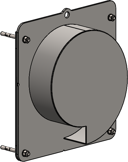
 FIXED LIMITERThe FIXED LIMITER is installed directly on the concrete wall. It is not removable. Access to the limiter for maintenance requires to going down into the access hole.
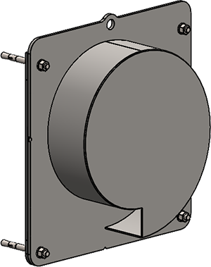
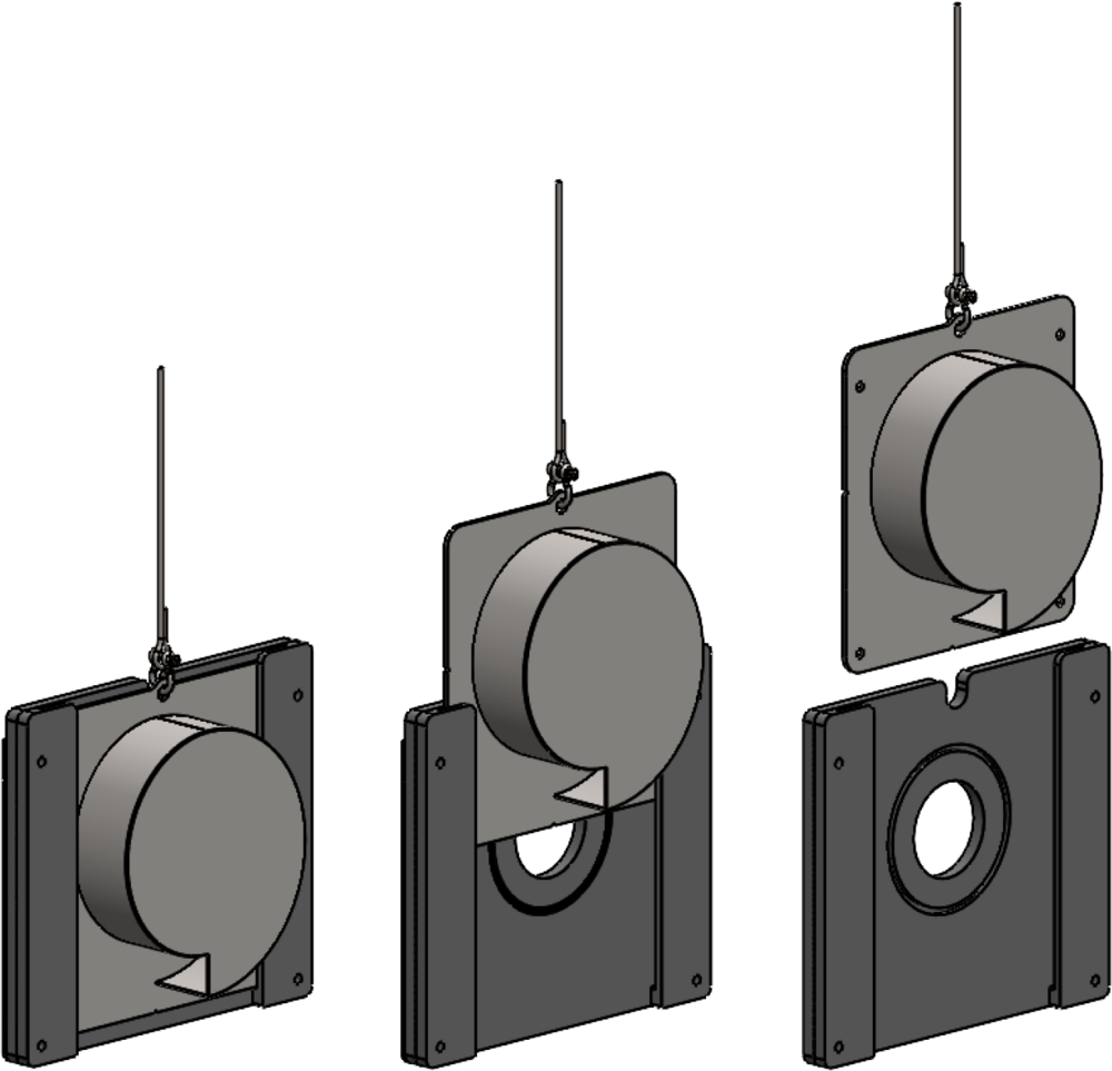 REMOVABLE LIMITERThe REMOVABLE LIMITER consists of a stainless steel body mounted on an HDPE support with two sliders. It can be fitted with a 3m or 6m sling to allow the flow limiter to be removed from the top of the access hole. This simplifies maintenance operations, as the limiter body can be cleaned from the surface. What's more, once the body has been removed, the flow is no longer limited, as the passageway is unobstructed.
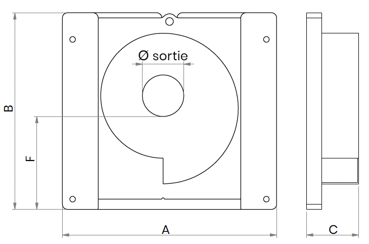
FIXED LIMITER PRODUCT REFERENCES
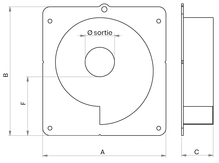
| REF. | A | B | C | F | Ø MIN(1) | Ø MAX(1) |
|---|---|---|---|---|---|---|
| LMVORTEX220 | 227 | 280 | 63 | 130 | 50 | 130 |
| LMVORTEX244 | 299 | 304 | 71 | 140 | 60 | 150 |
| LMVORTEX258 | 310 | 318 | 76 | 146 | 70 | 160 |
| LMVORTEX276 | 324 | 336 | 80 | 155 | 80 | 170 |
| LMVORTEX294 | 339 | 354 | 87 | 162 | 90 | 185 |
| LMVORTEX334 | 374 | 394 | 95 | 182 | 100 | 215 |
| LMVORTEX364 | 402 | 424 | 104 | 196 | 110 | 240 |
| LMVORTEX394 | 449 | 469 | 115 | 222 | 115 | 260 |
| LMVORTEX452 | 500 | 527 | 128 | 250 | 125 | 300 |
| LMVORTEX482 | 527 | 557 | 132 | 264 | 140 | 330 |
| LMVORTEX504 | 547 | 579 | 142 | 273 | 150 | 350 |
(1) Ø min. and Ø max.of the hole in limiter’s wall.
REMOVABLE LIMITER PRODUCT REFERENCES
↵
| REF. SUPPORT | REF. BODY | A | B | C | F | Ø MIN(1) | Ø MAX(1) |
|---|---|---|---|---|---|---|---|
| LMVORTEX220 | LMVORTEX220 | 357 | 310 | 124 | 145 | 50 | 130 |
| LMVORTEX244 | LMVORTEX244 | 379 | 334 | 138 | 155 | 60 | 150 |
| LMVORTEX258 | LMVORTEX258 | 390 | 348 | 148 | 161 | 70 | 160 |
| LMVORTEX276 | LMVORTEX276 | 404 | 366 | 160 | 170 | 80 | 170 |
| LMVORTEX294 | LMVORTEX294 | 419 | 384 | 172 | 177 | 90 | 185 |
| LMVORTEX334 | LMVORTEX334 | 454 | 424 | 172 | 197 | 100 | 215 |
| LMVORTEX364 | LMVORTEX364 | 482 | 454 | 190 | 211 | 110 | 240 |
| LMVORTEX394 | LMVORTEX394 | 529 | 510 | 223 | 247 | 115 | 260 |
| LMVORTEX452 | LMVORTEX452 | 580 | 567 | 233 | 275 | 125 | 300 |
| LMVORTEX482 | LMVORTEX482 | 607 | 597 | 253 | 289 | 140 | 330 |
| LMVORTEX504 | LMVORTEX504 | 627 | 619 | 264 | 298 | 150 | 350 |
(1) Ø min. and Ø max.of the hole in limiter’s wall.