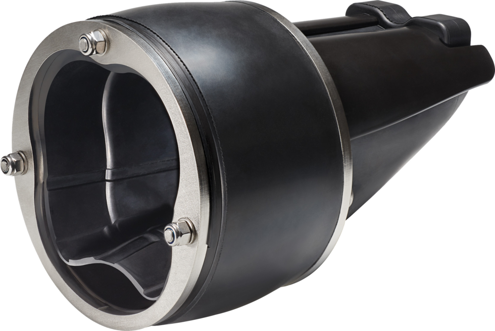
OZO® Inside Pipe Valve
Protection against backflow flooding rainwater and wastewater (1) networks in public, private and industrial infrastructures is a priority and a necessity. On existing networks, the installation of flap check valves may be limited by:
• difficult access to the installation;
• the absence of water fall (a culvert, etc.);
• a sloping or uneven surface that prevents surface- mounted installations (damaged surface, etc.).
For these and all other configurations, OZO® is the ideal solution, because it can be installed inside the pipe itself, whatever the material, in the rainwater and wastewater networks(1).
Quick and easy to install, it provides optimum protection for homes and buildings against flooding.
Unpleasant odours from the sewer system are also confined to the pipe thanks to the check valve's innovative, patented membrane.
(1) As with any network-integrated solution, it is essential to check and clean the inside pipe valve regularly to prevent the build-up of debris or waste that could compromise the valve's operation. Please contact us for more information.
DOCUMENTATION TO DOWNLOAD
OZO - INSIDE CHECK VALVE.pdf [pdf] - 2.95 MoCONCEPTION
The design of all OZO® valves is carried out by our R&D department.
It has the calculation means (CAD) to model the hydraulic and mechanical behavior of each valve.
Each new design is also tested and proven on test benches in order to validate its behavior under maximum pressure.
TECHNICAL DATA
- Body: PP loaded with glass beads (30%);
- Membrane and ring: EPDM;
- Fasteners: A4 stainless steel;
- Compression plates: AISI 304 stainless steel;
- Pressure resistance: up to 0.3 bars (3 mCE);
- ND: available from ND 100 to 200.
| REF | ND | DIAM INT. MINI | DIAM INT. MAXIMUM | HC (MMCE) | P (MCE) | A | B | C | D | WEIGHT (KG) |
|---|---|---|---|---|---|---|---|---|---|---|
| OZO_100_1 | 100 | 93 | 98 | 90 | 3 | 144 | 75 | 5 | 93 | 0,37 |
| OZO_100_2 | 100 | 98 | 103 | 90 | 3 | 144 | 75 | 9 | 98 | 0,45 |
| OZO_125_1 | 125 | 114 | 119 | 95 | 3 | 164 | 80 | 10 | 114 | 0,65 |
| OZO_125_2 | 125 | 123 | 128 | 95 | 3 | 164 | 80 | 11 | 123 | 0,90 |
| OZO_160_1 | 150 | 140 | 145 | 150 | 3 | 217 | 95 | 12 | 140 | 1,20 |
| OZO_160_2 | 150 | 147 | 152 | 150 | 3 | 217 | 95 | 13 | 147 | 1,50 |
| OZO_200_1 | 200 | 182 | 187 | 150 | 3 | 286 | 110 | 18 | 182 | 2,60 |
| OZO_200_2 | 200 | 198 | 203 | 150 | 3 | 286 | 110 | 20 | 198 | 3,70 |
HC: “flush” pressure = water height required to completely open the membrane.
P: maximum counter pressure that the OZO® resists.
INSTALLATION / APPLICATION
Depending on the on-site installation configuration, OZO® valves can be installed in both directions, at the inlet or outlet of the manhole.
Find information on installing OZO® valves in the documentation or via the installation instruction sheet provided with each valve.
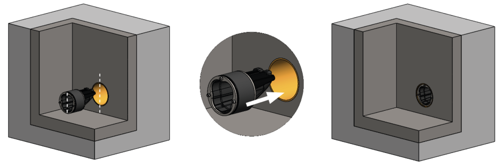 STEP 1Align the mark on the top of the flap with the top of the pipe. Insert the flap inside the pipe.
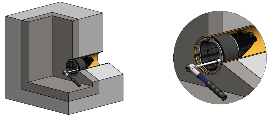 STEP 2Tighten the fasteners to the recommended torque.
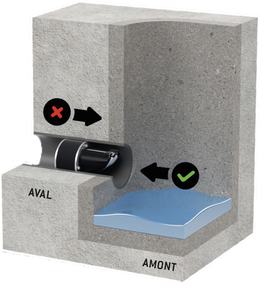 INSTALLATION CONFIGURATION 1: DOWNSTREAM OF THE PIPELINEThis is the standard delivery configuration.
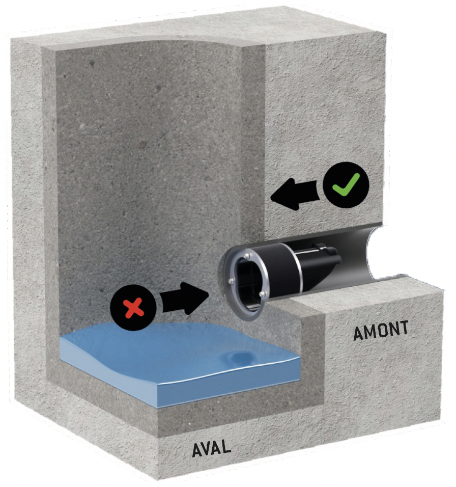 INSTALLATION CONFIGURATION 2: UPSTREAM OF THE PIPELINE
OPERATION
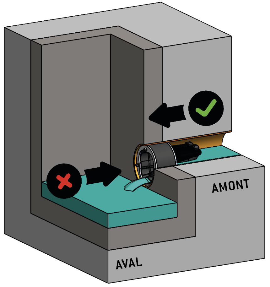 NORMAL DIRECTION OF DISCHARGE: OZO® OPENINGA. The check valve allows a single stream of water to drain out. B. When the water level upstream of the membrane reaches the opening pressure (HC rating), the ‘flushing’ effect cleans the pipe downstream of the OZO®. C. Once the membrane is fully open, the flow is drained off.
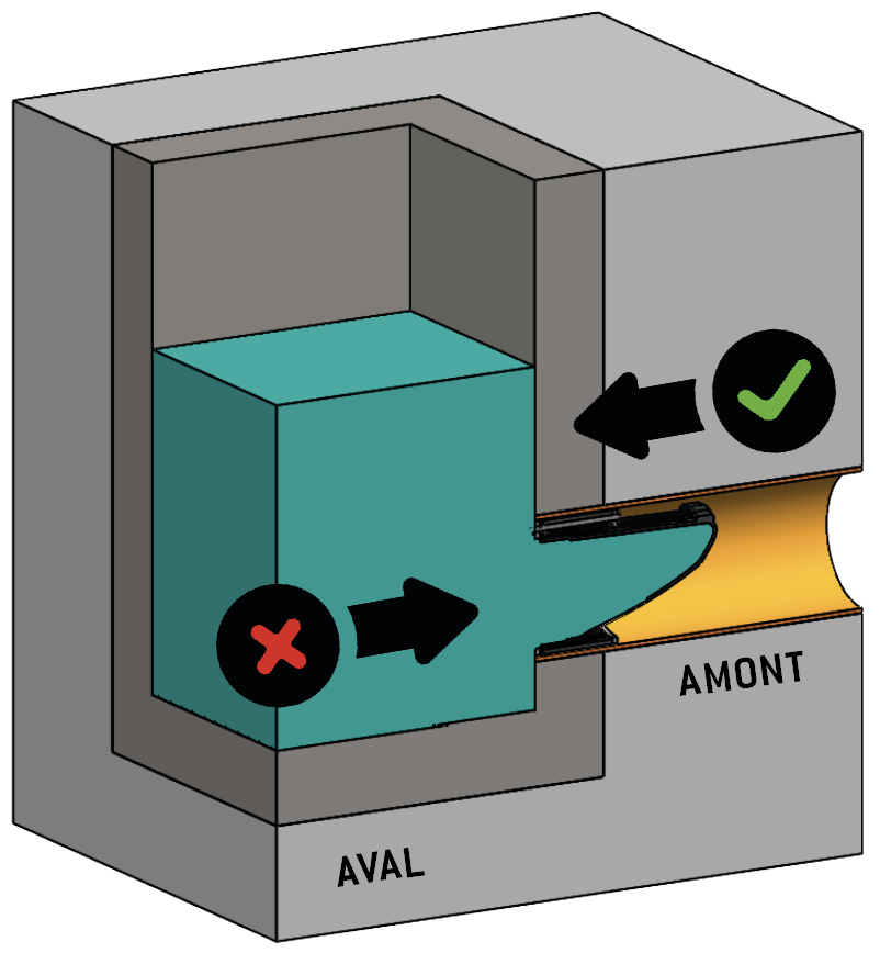 BACKFLOW: OZO® CLOSINGIn the event of backflow, the membrane completely blocks the backflow and prevents flooding. Upstream is perfectly protected.
ANTI-SMELL PROTECTION
As standard, the OZO® valve membrane is in the closed position, which stops odors from rising.
Bad odors thus remain confined inside the manhole.