MULTI Anti-backflow valve
Specifications
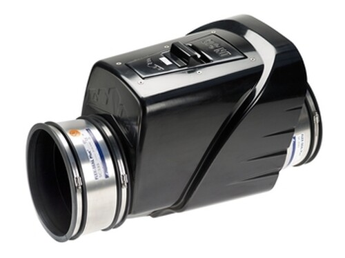
MULTI is a non-return valve used within sewerage and drainage systems to eliminate the risk of flood damage by the backflow of sewage or flood water into properties through low level entries such as drain gullies.
It incorporates a flap or door which is opened or closed by the flow of water.
- When water flows normally, from upstream to downstream, the water pushes the flap in the opening direction and the water flows freely.
- When the reverse happens and the water starts to backflow due to flooding , the water pushes the flap into the closing direction and is stopped at this point.
Available from ND 250 to ND 500 mm, the MULTI non-return valve can be connected to any type of pipeline using the NORHAM Flexible multi-material couplings.
The materials from which the MULTI valves are made make the parts far lighter than the traditional valves as well as quick and easy to handle and install.
They are very highly resistant to corrosion, UV light, thermal shocks and mechanical stress.
- The MULTI valve body is made from glass fibre reinforced isophtal acid polyester and coated in an isophtal acid Gel-Coat.
- The axle is ERTACETAL (POM), the seals EPDM (option oil-resistant nitrile rubber, apart from ND 315) and grade 1.4401 (316) stainless steel fastenings.
- The MULTI non-return valve can withstand pressures of 0.9 bar.
- A mechanism without counterweight, it offers very good sealing criteria.
New locking system
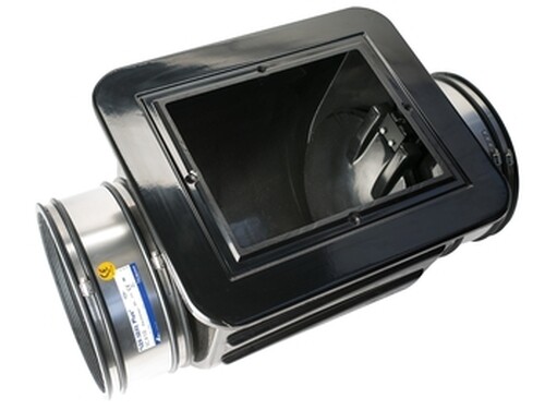 1 – Inspection panel removed
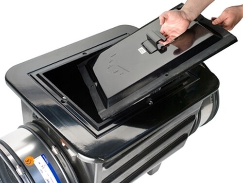 2 – Introduce through the panel and insert it fully into the valve
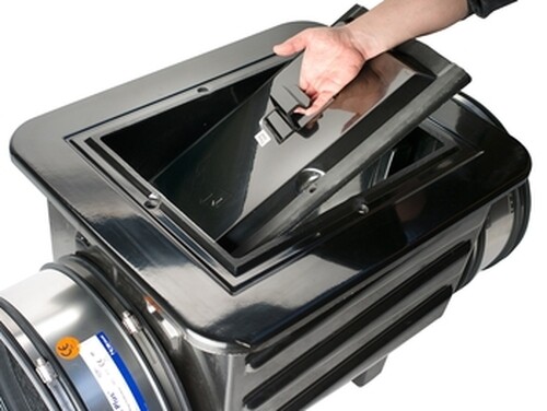 Positioning of the panel: join the seal to the upstream part of the valve (on the swing side)
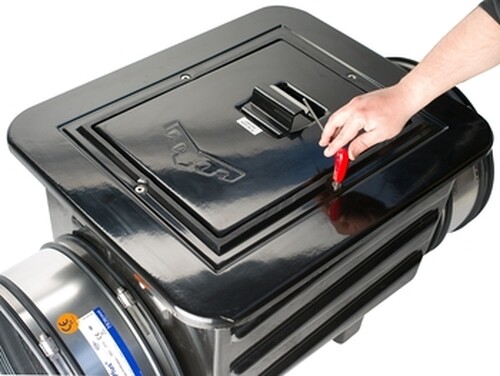 3 – Once the panel is installed, lock it in by screwing in the 4 fastenings
The brand new design MULTI 400 and 500 in-line valves, engineered by NORHAM, makes the device even more compact, lightweight, easy to inspect and optimally watertight!
Design DN 250 - 315 - 400 - 500
Installation / Application
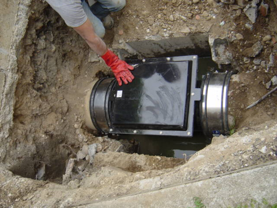
Installing the MULTI non-return valve is quick and easy.
- Firstly, cut a section of the pipeline at the point where the in-line valve will be installed, 20 mm longer than the length of the valve (e.g.: for a MULTI 250 valve – the valve’s length is 730 mm - the section to be cut will therefore measure 730 + 20 = 750 mm).
- Then draw a line on the ends of the pipeline being connected, representing half the width of the coupling (e.g.: for a NORHAM Flexible Couplings SC275 coupling – the couplings width is 150 mm – the mark will therefore be drawn at 150/2 = 75 mm from the end of the pipeline).
- Loosen the fastenings and place the NORHAM Flexible Couplings onto the pipe end piece (without lubricants or glue).
- Finally, align the valve between the two parts of the pipeline being connected, move the NORHAM Flexible Couplings up to the marks drawn and tighten all the fastenings of the couplings until they are locked.
The inspection panel of the MULTI in-line valves is fastened using screws and wing nuts (ND250) or a stainless steel (A4 type) hex head screw (ND 315, 400 and 500).
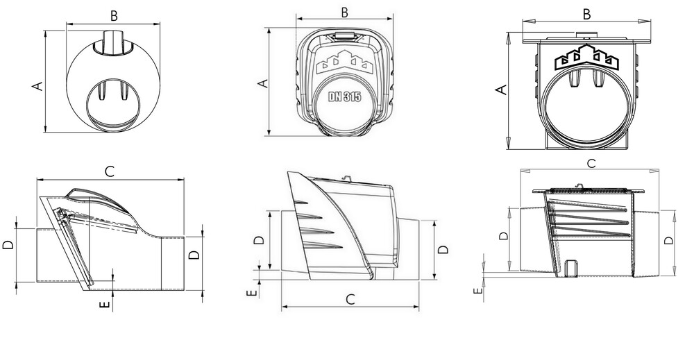
Dimensions
| Ref | ND | A (mm) | B (mm) | C (mm) | D (mm) | E (mm) | Weights (kg) |
|---|---|---|---|---|---|---|---|
| MULTI-250 | 250 | 485 | 455 | 730 | 260 | 60 | 15 |
| MULTI-315 | 300 | 572 | 525 | 735 | 316 | 52 | 16 |
| MULTI-400 | 400 | 600 | 610 | 900 | 410 | 30 | 32 |
| MULTI-500 | 500 | 730 | 700 | 1230 | 515 | 40 | 59 |