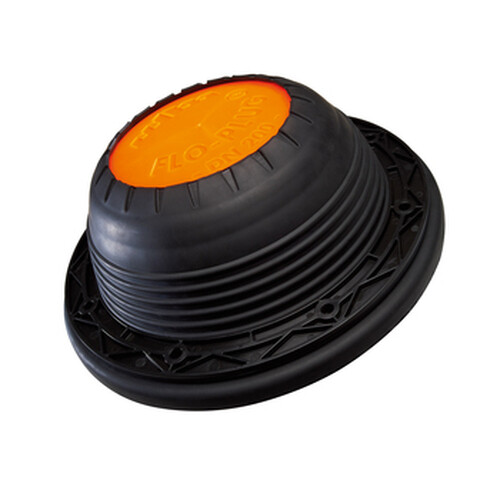
FLO-PLUG® Tank floor protection valve
Specifications
FLO-PLUG® 2 was engineered and patented by NORHAM in 2007 to provide a professional solution for preventing the mechanical damage caused to the bottoms of tanks when groundwater and gas rises particularly when the tank is empty.
With no moving parts, the tank floor protection device, FLO-PLUG® 2 is comprised of:
- A “hat-shaped” body, with holes drilled all over its periphery, made from PP Homopolymer, with a UV-resistant coating.
- and an EPDM membrane that covers it.
Thanks to the materials chosen for its manufacture, the FLO-PLUG® 2 device is highly resistant to:
- pressure,
- corrosion,
- mechanical stress,
- UV light,
- sewage,
- and withstands temperatures ranging from -40°C to + 90°C.
FLO-PLUG® 2 offers a feed-through flow rate of 5,000 l/h (for concrete basins/tanks - 4000l/h for geomembrane basins) for a pressure loss (groundwater pressure or gas pressure needed for opening the valve) of 60 mbar (60 mm head).
To calculate the number of tank floor valves needed for your application, use our data sheet to help your or contact us for a customised specification.
WORKING PRINCIPLES
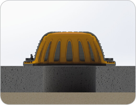 Stage 0 – Tank empty
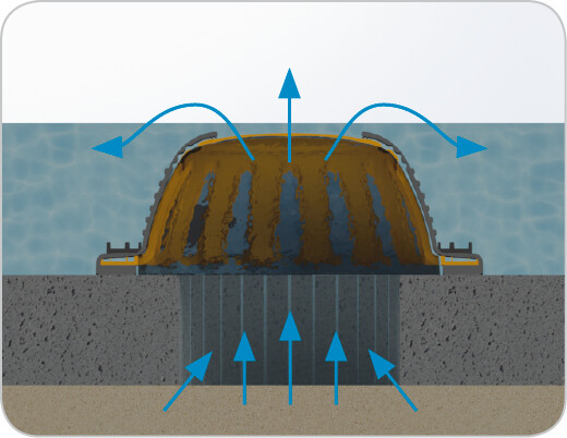 Stage 1 – Groundwater or gas risingWhen the water tables or gases rise, the membrane is isolated from the body of the FLO-PLUG® 2 to allow the water and gases to pass through.
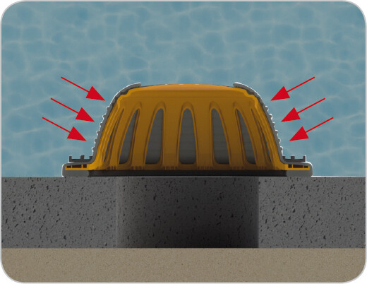 Stage 2 – Tank fullOnce the tank is full, the weight of the water contained in the tank, flattens the membrane against the valve body. The holes are now sealed, which prevents the water draining from the tank. FLO-PLUG® 2 ensures a good watertight seal ensuring no contamination of the surrounding ground or groundwater from the contents of the tank.
APPLICATION / INSTALLATION
APPLICATION
The FLO-PLUG® 2 tank floor valve is ideal for holding tanks.
It can be set up on:
- concrete structures,
- geomembrane tanks
- or on other water storage facilities (reservoirs, vats ...).
For a geomembrane application, it is necessary to ballast the tank floor.
Make sure to have backfill materials and a spacer in this case (provided by us on request).

Contrary to the traditional free-standing tank floor valves, FLO-PLUG® 2 is
- extremely space-saving,
- lightweight (only 1.5 kg),
- and easy to set up!
A stand-alone safety element, once installed, it requires very little servicing.
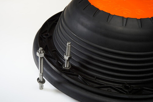
The fastenings provided with the FLO-PLUG® 2 tank valves are made from grade 1.4401 (316) stainless steel for a better durability over time.
INSTALLATION
The FLO-PLUG® 2 device for rising groundwater and gases is suitable for both:
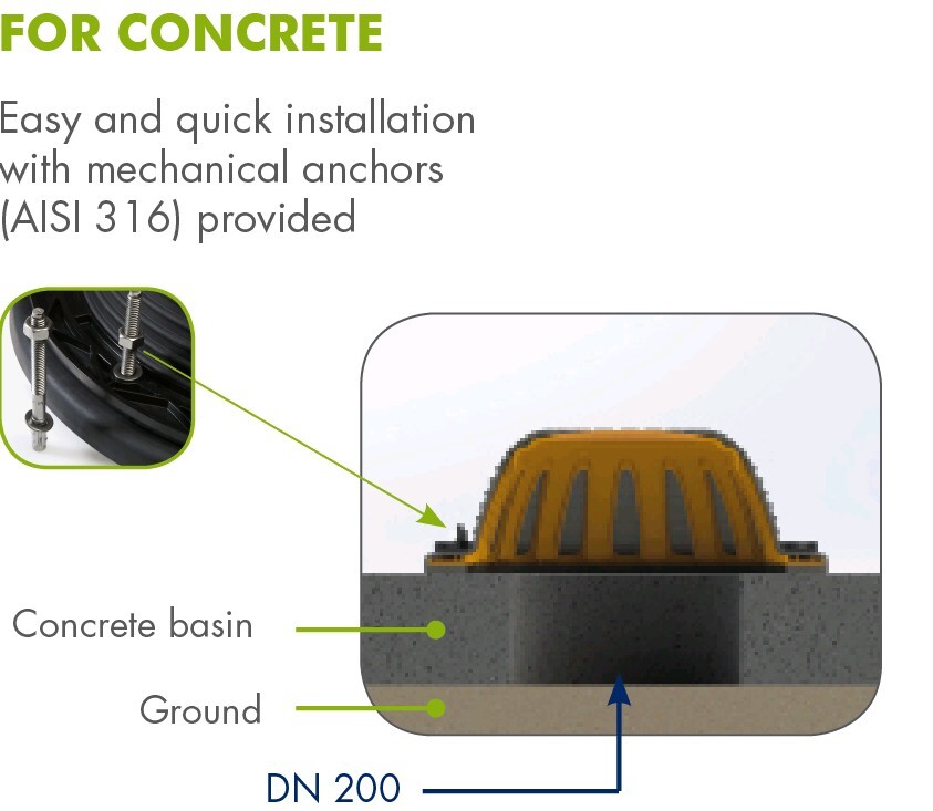
Hard floors (e.g.: concrete tank).
The setting up of FLO-PLUG® 2 tank floor valves onto a concrete slab is very simple.
- Make sure, firstly, that the support on which the FLO-PLUG® 2 will be installed is perfectly even, clean and smooth.
- Also, make sure that the hole in the concrete slab is no larger than 200 mm in diameter.
- Then place the body of the valve onto the wall, centre it and mark the fastening points found on the flange.
- Drill at Ø 8 mm and 65 mm in depth and put the bolts into position.
- Reposition the valve body onto the set fastenings and tighten all of the bolts evenly – Torque setting: 12 N.m
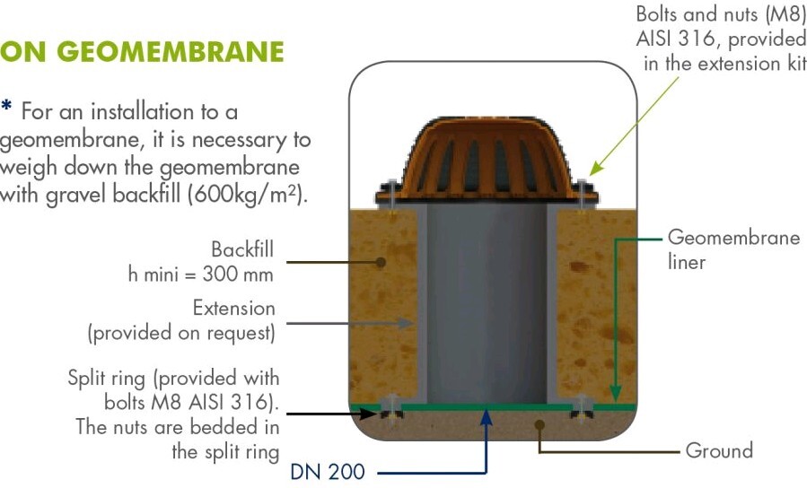
Supple floors (e.g.: watertight geomembrane water reserve).
Geomembrane also require a companion flange.
This is delivered with the FLO-PLUG® 2 valve for geomembrane tank.
If it becomes necessary to ballast the geomembrane with the backfill material (or equivalent), a spacer between the geomembrane and the Flo-Plug™ must be installed (ask us).
The necessary tools are as follows:
- a drill and Ø8 mm drill bit,
- a 13 torque wrench, a hammer,
- and 8 x Ø8 bolts (supplied with the FLO-PLUG® 2 tank valve).
For an application on a flexible floor, the adapter flange as well as the special (M8) screws and bolts are provided with the product.
DIMENSIONS
FLO-PLUG® 2 is available in ND 200.